Blackboard FPGA Training Board: Just Follow !! 무조건 따라하기!!
Pre-requisite
Parameter |
Requirements |
|---|---|
PC requirement |
i3 or higher processor 20 GB for compiler 1GB for projects |
OS |
Windows 7 or higher (32 or 64) |
Simulation Software |
Modelsim 3.6f |
FPGA compiler |
Quartus 13 or higher (32 or 64) |
Black board |
Board Power Supply USB wire |
Pre-requisite
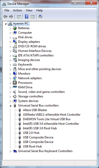
| ○ When you connect the board first time you have to install the byte blaster to program the board correctly. csa ○ Before connecting the board, install the Quartus project ○ The Driver is located at ●"\" system_drive :/\Quartus_type/\Quartus_version/\quartus/\drivers" ●"C:\altera_lite\16.0\quartus\drivers " ○ Confirm the device is recognized by system |
 |
Making Project Directory
| ○ Choose any suitable location on the working drive. ○ Make following folder hierarchy as shown below: 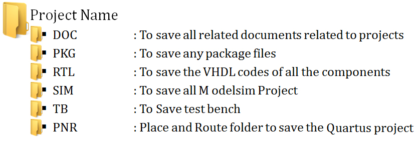 ○ Make sure the Folder names must not contain non English characters, space or any other special character other than '_' (underscore) |
Create a New Project (1)
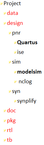
| ○ Create a new directory and copy the design files for this lesson into it. ●Start by creating a new directory for this exercise (in case other users will be working with these lessons). ●It is recommended to have following set of folder for efficient method of design as shown. ●After making the basic folder system, it is always just copy the complete folder and make new combination with name of the project. ●In this example we have the project name as "test" so change the name of parent folder to "test". |
 |
Create a New Project (2)
| ○ When you turn on Modelsim the following screen appears. ○ Designer can click on Jumpstart and choose the options for creating new project. ○ If this option is off just go to next slides. ○ Create new project as shown below 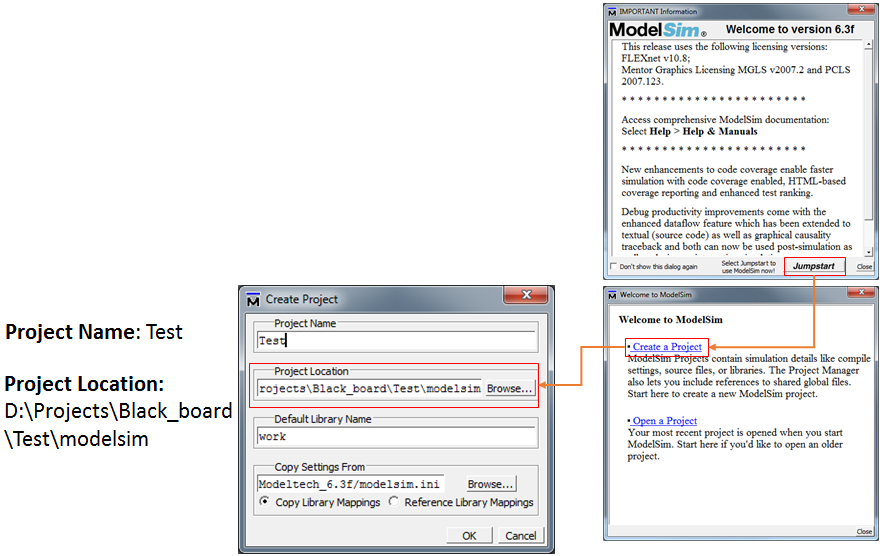 |
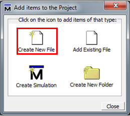
Adding new file
1.Click on “Create New File”
|
 |
2.In File Name: ../RTL/Mygate.vhd
○This will make Mygate.vhd file in RTL folder
○You can browse to select the directory where you want to keep the VHD files too. |
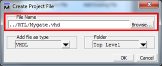 |
3.Click OK, to continue
|
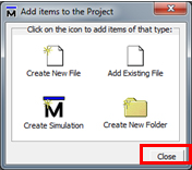 |
○ The “Add items..” menu will reappear.
○ If you want to add more file follow same procedure (1. to 3.)
○ When done with adding files click “Close” |
Writing the VHDL code
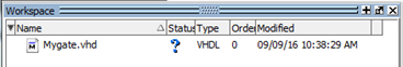
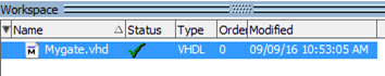
○ The added file will appear in Workspace window
|
 |
○ Double click the File or right click and click on “Edit”
|
 |
○ File will be open in the Editor
○ Write a simple code as shown in Next slide
● (you can simply copy paste for speeding up the process)
○Lot od simple examples are available in following site
|
|
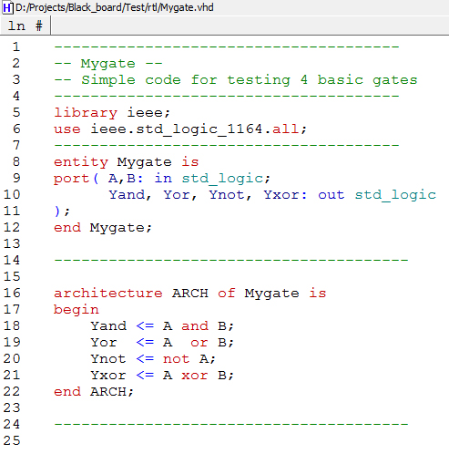
Mygate.vhd
-------------------------------------- -- Mygate -- -- Simple code for testing 4 basic gates -------------------------------------- library ieee; use ieee.std_logic_1164.all; -------------------------------------- entity Mygate is port( A,B: in std_logic; Yand, Yor, Ynot, Yxor: out std_logic ); end Mygate; --------------------------------------- architecture ARCH of Mygate is begin Yand <= A and B; Yor <= A or B; Ynot <= not A; Yxor <= A xor B; end ARCH; --------------------------------------- |
 |
○ Thank Save the file (CTrl + S) or press
|
 |
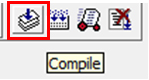
Compiling the Code
○ Click compile button |
 |
○ Or you can use menu
●Compile > Compile Selected |
|
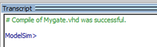
○ If there are no errors you will get following message on the Transcript window |
 |
○ The status of the code will be |
 |
○ Now you are ready for Simulation |
Simulation
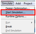
○ Click Simulate -> Start Simulation |
 |
○ Click on the Work -> myagte |
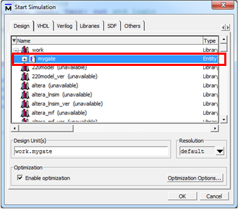 |
○ Click "OK" |
|
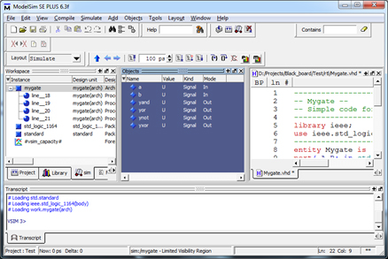
○ The Layout will change to Simulation mode |
 |
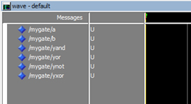
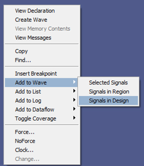
○ ●Add to wave > Signals in Design
-It will add all signals to the Simulation window
 |
 |
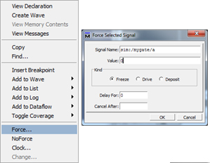
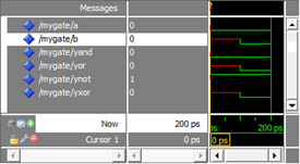
○Assigning values to input signal
●
●Change “Value” from “U” to “0”
●Click “OK” |
 |
○Run simulation
●Click |
More Simulation
○ The Window will look like |
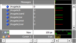 |
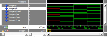
○ Like wise change Force the value for the Input signal "b" to 0 first and run simulation |
 |
○ Now change both Signals to '1' and verify the outputs are matching to the gate behavior |
 |
Putting code to FPGA
Quartus Project
○ Once the code is functionally verified we can put the code to FPGA |
○ For FPGA we will have following configuration 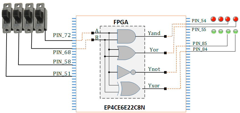 |
Start Quartus project
○ Start the Quartus project ●Start -> Quartus [Software] 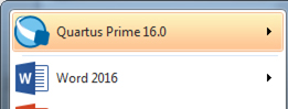 |
○ Click on "New Project Wizard" 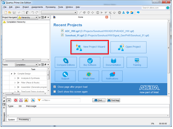 |
Making Quartus Project
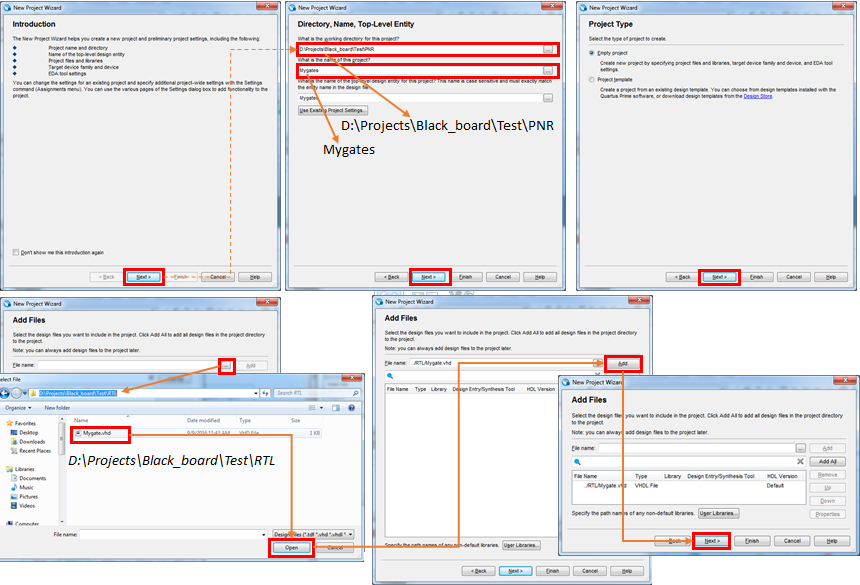
|
Finalizing the Project making
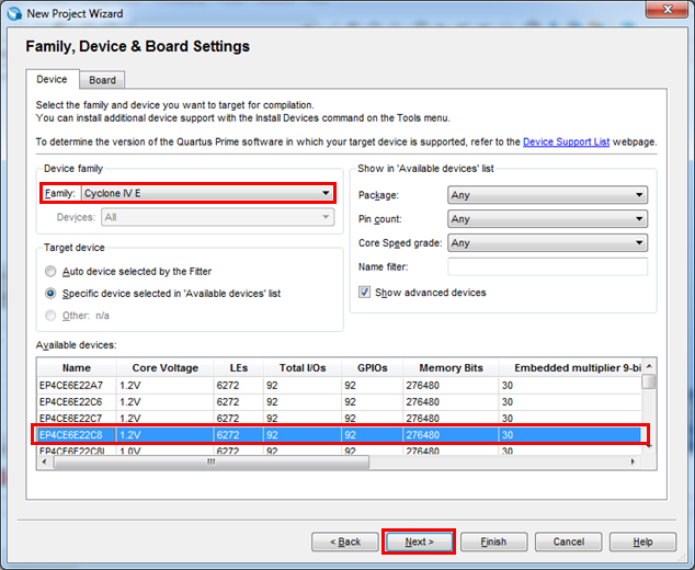
○ Device Family: Cyclone IVE
○ Available Device: EP4CE6E22C8N
○ Press Next
| 
|
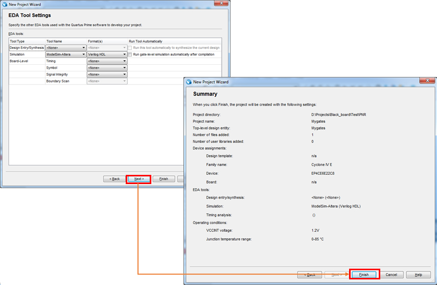
Finalizing the Project making
|
Quartus Project
○ Click at Project Navigator ●Change Hierarchy to Files 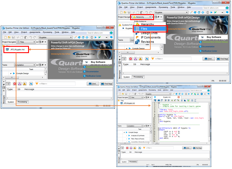 |
○ Double Click on the Mygate.vhd file ● It will open file in Quartus editor |
IMPORANT: Setting top entity
○ And in menu select ●Set as Top-Level Entity 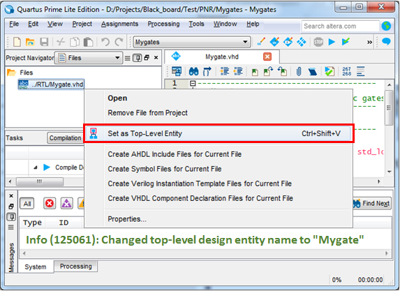 |
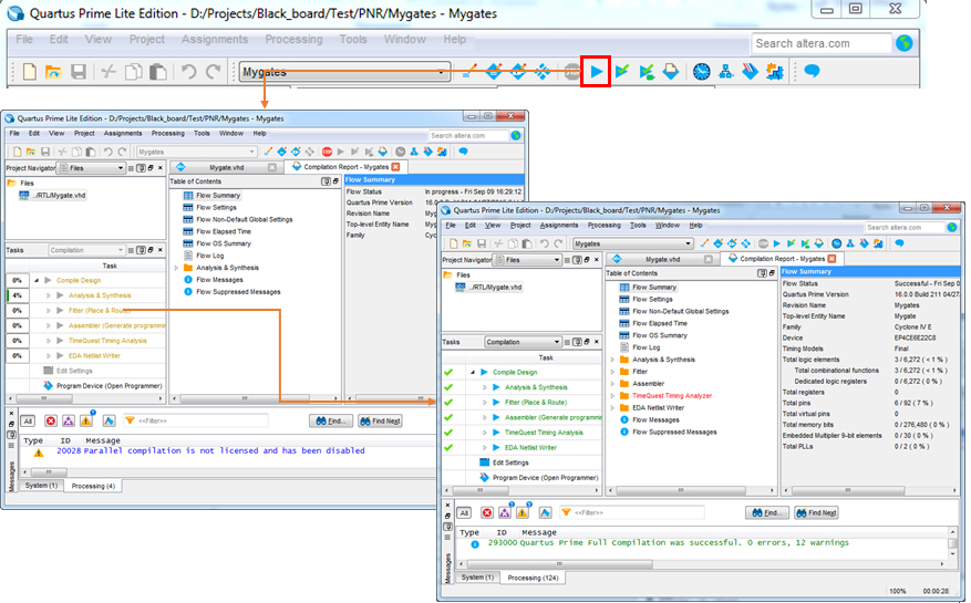
Compile
 |
Pin Assignment
○ Now we have to assign the ports of our design to respective pins 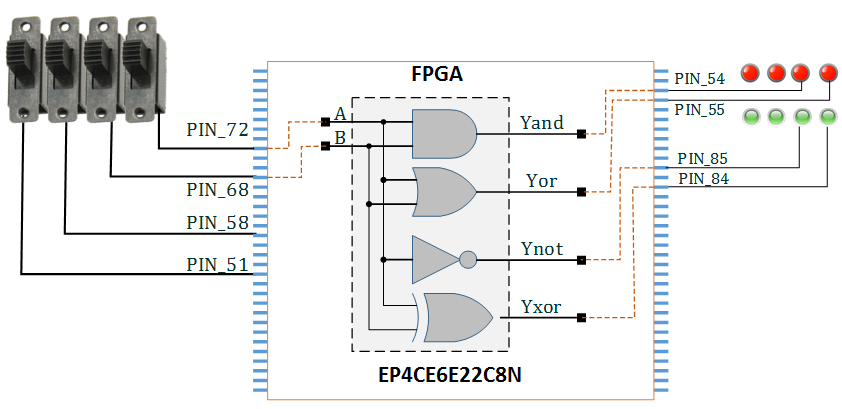 |
○ Click on the Pin Planner icon 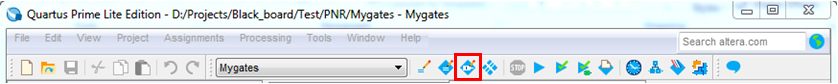 |
|
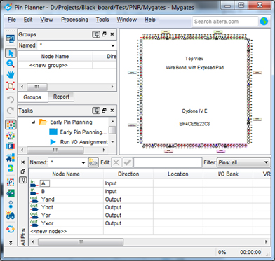
○ Following window will appear
| 
|
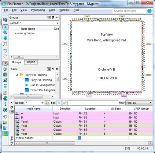
○ In this window write the corresponding pins in the location column
●See Next page
| |
○ Trick: You can skip typing "PIN_" and just type the pin number like 72, 68…(Quartus auto complete it)
| 
|
○ After assigning pins COMPILE AGAIN
| |
○ If it as to save anything, save it (choose Yes)
| 
|
Programing the FPGA
○ Connect the Byte blaster to JTAG
○ Connect USB of Byte blaster to the Host PC ○ Connect the power to the system 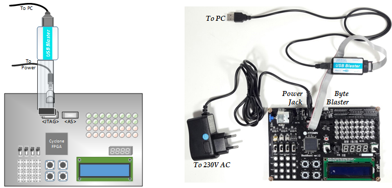 |
○ Turn on the board
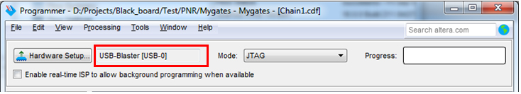
○ Click on the Programmer Icon ○ If your Byte blaster is correctly installed you will get following window  ●If you don't get USB Blaster written go to slide 3
 |
Selecting file to Program
○In the "Programmer" Window
○ Click "Add file" button ●Browse to "output_files ●Open "Mygates.sof" file ●Like this you can program any Sof file directly 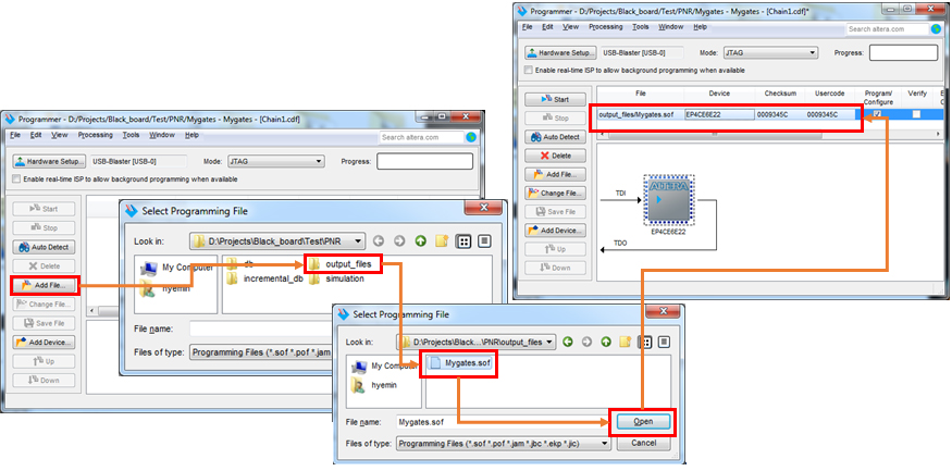 |
Putting Code in FPGA
○ Click the Start Button
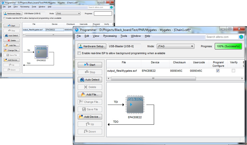 |
○ Now your Black board is ready to use |
Testing
○ Now toggle the switches and see effects on the LED
○ Make sure that on side of LED the jumper is connected.
○ If jumper is not connected the LED will be disconnected and the upper expansion slot will work
|
Future
○ Likewise you can program any code and use it
|
Buying Black Board
○ Black Board is available for buying
○ For cost and payment contact: ●SK TechnoPark N-1005, Sungsan-dong 77-1, Sungsangu, Changwon, Kyoungnam, South Korea ●Tel; 82-55-600-6166 ●Fax; 82-55-600-6167 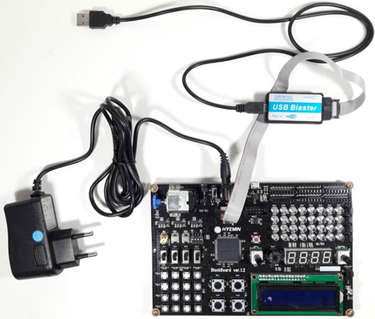 |